
Content
A lever float steam trap represents one of the most reliable mechanical solutions for condensate removal in industrial steam systems. These devices operate on a simple yet effective principle: using buoyancy forces to sense the presence of condensate and automatically discharge it while blocking live steam escape. This makes them indispensable in textile mills, pharmaceutical manufacturing, food processing facilities, and chemical plants where precise condensate management directly impacts energy efficiency and equipment longevity.
Unlike thermostatic or inverted bucket designs, float steam trap systems excel at handling high condensate loads with minimal maintenance requirements. The absence of complex moving parts means fewer failure points and lower lifecycle costs over 15 to 20 years of continuous operation.
At the heart of every lever float steam trap lies a simple mechanical concept: condensate detection through displacement. When condensate accumulates in the trap body, it raises the buoyancy of the internal float chamber. As the float rises in response to the increasing liquid level, it mechanically activates a lever system connected to the discharge valve.
This lever amplifies the upward force from the float, translating modest buoyancy into sufficient mechanical advantage to open the main valve seat against the pressure differential across the trap. A typical lever ratio of 3:1 to 5:1 ensures that even light condensate accumulation generates adequate opening force.
Once the valve opens, condensate flows out through the discharge port under the pressure differential between the steam chamber and the return line. Flow continues as long as condensate remains present and the float stays elevated. The discharge rate depends on valve lift height, orifice diameter, and pressure drop across the trap.
As condensate drains, the liquid level drops inside the trap body. The float descends with the falling condensate level, and the lever mechanism gradually reduces valve opening. Once all condensate is expelled, the float rests at its lowest position, and a spring-loaded or pilot-operated mechanism snaps the valve shut, sealing against live steam ingress.
Modern lever float steam traps utilize three primary materials depending on operating conditions:
The float chamber is machined or cast as a sealed cavity within the trap body. Its volume and shape determine the float's effective buoyancy and the condensate level at which the trap responds. Larger chambers provide more stable, damped operation suitable for fluctuating steam loads, while compact designs respond quickly to condensate generation. The chamber must resist corrosion from acidic condensate; many manufacturers apply protective coatings or select corrosion-resistant material combinations.
A precision-machined pivot point allows the lever to rotate freely without binding. The lever itself is typically made from cast iron or ductile iron, hardened at high-stress zones. The connection between the float rod and lever arm incorporates mechanical stops to prevent over-travel and rupture. Some advanced designs use needle bearings at the pivot to reduce friction and extend maintenance intervals.
The valve disc must seal reliably under pressures ranging from near-atmospheric to 40 bar. Most lever float traps employ a soft seat design using elastomer or PTFE rings that accommodate minor surface imperfections. Hard-seated alternatives with stainless steel or tungsten carbide faces suit applications with abrasive or sticky condensate. The valve seat bore is precision-ground to ensure concentric sealing and minimal leakage.
Combining lever float action with a thermostatic element addresses one weakness of pure float traps: their inability to handle air purging during startup. Float-thermostatic hybrids integrate a bimetal strip or capsule that opens independently when condensate temperature drops below saturation, allowing trapped air to escape. This prevents air binding in steam lines and delivers superior performance during system warm-up phases.
Standard vertical or angle-pattern bodies suit branch line applications where condensate flows downward into the trap. Horizontal or inverted configurations work for steam pipes installed below the plant floor or in spaces where vertical mounting is impractical. The float chamber orientation changes, but the basic lever principle remains identical.
Manufacturers offer multiple orifice diameters (typically 3 mm to 12 mm) to match the expected condensate load. A trap sized too small will back up condensate and cause water hammer; oversized traps discharge steam waste and reduce efficiency. Proper sizing requires calculating condensate generation rate in kg/h based on steam input, process load, and insulation quality.
Lever float steam traps operate efficiently across a wide pressure spectrum. Low-pressure applications (0.5 to 2 bar) benefit from the trap's sensitivity to small condensate volumes. Medium-pressure services (2 to 10 bar) represent the optimal operating zone where float response remains quick and wear is minimized. High-pressure operation (10 to 40 bar) demands robust materials and careful valve seat selection to withstand erosive discharge velocities.
A single float trap typically handles 200 to 2000 kg/h of condensate depending on size and pressure rating. Unlike thermostatic traps that struggle with variable loads, lever float designs maintain stable discharge rates across condensate volume swings. This makes them ideal for batch processes or applications where steam demand fluctuates hourly.
Condensate generation and discharge cycles repeat continuously during operation. A well-tuned lever trap responds within 15 to 30 seconds of condensate accumulation, minimizing backup and avoiding water hammer. Cycling frequency depends on trap size relative to steam line diameter; typical industrial installations cycle once every 2 to 5 minutes during steady operation.
Air present in steam lines creates challenges for all trap types. Pure float designs cannot vent air at saturation temperature because the float remains submerged in liquid. Combination designs with thermostatic elements overcome this by opening the pilot valve when condensate temperature drops, releasing trapped air before normal float operation resumes. Facilities experiencing chronic air binding should specify float-thermostatic traps or install dedicated air vents.
| Feature | Lever Float Trap | Inverted Bucket Trap | Thermostatic Trap |
|---|---|---|---|
| Condensate handling capacity | Excellent | Good | Limited at high loads |
| Air removal | Poor without thermostatic element | Automatic via bucket vent | Automatic via opening |
| Maintenance frequency | Low to moderate | Moderate to high | Moderate |
| Response to load changes | Very responsive | Good | Slower response |
| Cost | Moderate | Moderate | Low |
Float traps excel in applications where condensate generation varies throughout the shift. Food sterilization lines that operate in batches, textile dyeing machinery with cyclic heating, and chemical reactors with temperature swings all benefit from the float trap's proportional discharge response. As condensate flow increases, the float rises higher, opening the valve wider and increasing discharge rate proportionally.
The absence of moving bellows, bimetallic strips, or complex pilot systems reduces manufacturing complexity and extends service life. Field repairs often involve only seat grinding or float refurbishment rather than complete trap replacement. In facilities operating 50 or more traps, bulk maintenance and parts compatibility favor standardized mechanical steam trap designs.
Unlike some thermostatic designs that become sluggish or fail to discharge at extreme pressure swings, float traps maintain consistent operation from 0.5 bar to 40 bar. The buoyancy principle is independent of saturation temperature, making pressure changes transparent to trap function.
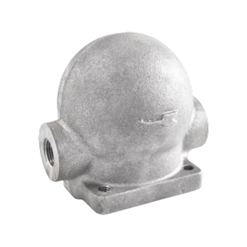
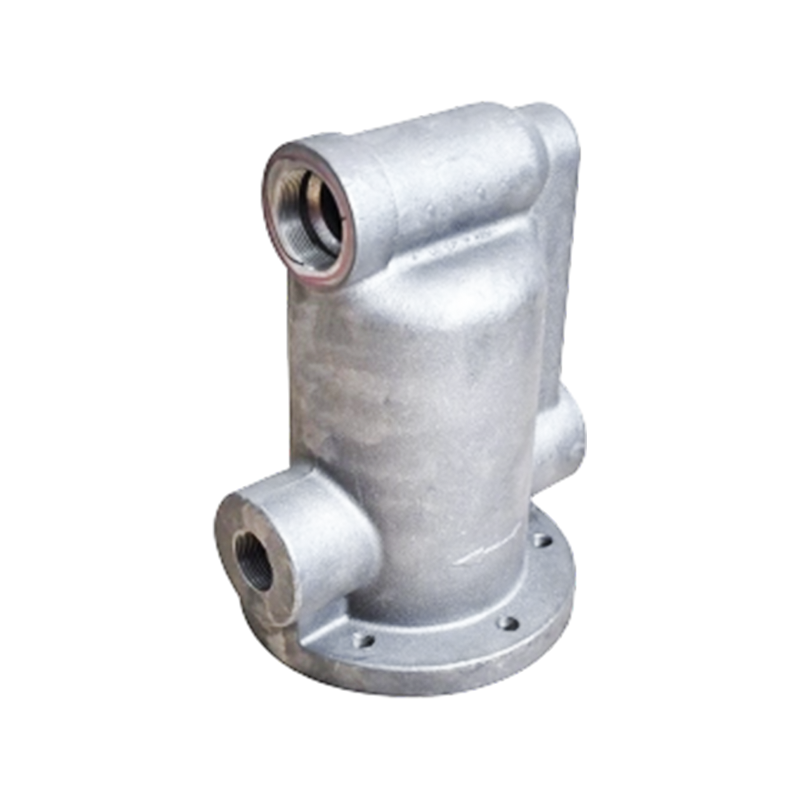
Most lever float trap bodies begin as iron castings produced through green sand casting methods. Sand casting allows cost-effective production of complex geometries including internal passages and float chambers. The sand mold is created by compacting specially prepared sand around a wooden or metal pattern. Molten cast iron is poured at approximately 1400°C and allowed to cool in the mold. After solidification, the casting is knocked out and gated runner removal begins.
Quality sand casting processes incorporate chemical analysis and mechanical testing of sample coupons cast from the same heat as production parts. Tensile strength verification, hardness mapping, and metallographic inspection ensure the casting meets strength specifications and contains no excessive porosity or inclusions that could cause field leaks.
After casting, components undergo precision machining to finish valve seats, bore float chambers, and create pivot holes within tight tolerances. Modern shops use CNC machines programmed to hold bore diameters to ±0.05 mm and seat runout to less than 0.1 mm total indicated runout. These tolerances are critical; excessive clearance leads to external leakage, while tight fits cause sticking during operation.
Assembly involves inserting the float, lever, springs, and valve disc into the body with careful attention to part orientation and spring preload. Hydrostatic tests at 1.5 times the rated working pressure validate that no internal leaks occur and that the valve seat seals reliably.
Manufacturers typically design and test traps to comply with international standards such as ISO 6704 for steam trap testing or PED directives for European market entry. Pressure equipment certification, material certs, and hydrostatic test documentation accompany each trap shipment to enable plant engineers to verify suitability and validate system safety.
Lever float steam traps must be installed at the lowest point in each steam line segment to allow gravity drainage. Horizontal steam pipes sloping toward the trap at a minimum 1:100 gradient ensure condensate reaches the trap entrance. Vertical or near-vertical risers require traps at the base; elevated branch lines need traps at endpoints to prevent condensate pooling and water hammer.
Isolating valve placement upstream of the trap allows for maintenance without venting the entire steam system. A downstream isolating valve on the return line provides additional safety and enables trap testing without disturbing downstream condensate recovery equipment.
When a steam system first pressurizes, large volumes of air and cool condensate flood the steam lines. The trap must expel this air to avoid water hammer and allow steam to reach process equipment. For systems without thermostatic elements, manual air vents or separate thermostatic air vents must be installed at high points to facilitate startup. After 15 to 30 minutes of venting, air has generally been purged and normal trap operation commences.
Weekly visual inspection checks for external leakage around the valve bonnet or float chamber. Any visible dripping indicates internal wear requiring maintenance. Listening for unusual sounds with a stethoscope reveals stuck floats or failing springs. Condensate return line temperature measurement confirms the trap is actively discharging; return lines should be noticeably warm to touch during normal operation.
After 10,000 to 15,000 hours of operation (typically 3 to 5 years), accumulated corrosion products or mineral deposits may reduce valve performance. Trap removal and disassembly reveals the float, lever, and valve disc. Light erosion can be addressed by careful lapping of the valve seat with fine grinding compound. Heavily corroded components are replaced with factory refurbished or new parts. Complete rebuilding kits containing all wear items are commercially available and significantly reduce downtime compared to full trap replacement.
After installation or rebuilding, the trap should be isolated and its discharge line routed to a test container. Opening the isolation valve allows condensate to flow for 5 minutes while checking for excessive steam carryover or water hammer events. The discharge should be predominantly warm condensate with occasional puffs of steam rather than continuous steam flow. If excessive steam discharge is observed, the valve seat may require relapping or the trap may be oversized for the application.
If condensate return lines experience pressure exceeding 0.5 bar absolute, the trap cannot fully open because back pressure opposes the discharge valve opening force. This causes condensate backup in the steam lines and potential water hammer. Solution: Install a parallel return line with check valve or reduce condensate elevation difference to minimize back pressure.
Corrosion or debris inside the float chamber can prevent smooth float movement, causing the trap to either fail open (steam waste) or fail closed (condensate backup). Disassembly and cleaning of the float chamber with fresh steam or hot water usually restores normal operation. Prevention involves maintaining system water treatment to minimize corrosion product generation.
Continuous steam discharge from the condensate outlet indicates a failed valve seat seal or undersized trap. First verify the trap is properly sized; if confirmed, the trap requires seat lapping or full rebuild. Severely scored seats may require valve disc and seat replacement.
If steam lines accumulate condensate despite the trap running, the trap orifice may be partially blocked by sediment or the discharge line may be restricted. Isolate and remove the trap for cleaning. Flush the discharge line with high-pressure water or steam to clear any blockages. Strainers installed upstream of the trap can prevent debris ingestion.
Small leaks around bonnet bolts indicate high internal pressure against the gasket seal. Verify the trap is correctly installed and operating below rated pressure. Gradual bolt tightening may restore the seal, but persistent weeping requires gasket replacement and possibly surface flattening if the casting shows corrosion damage.
Textile mills consume vast quantities of steam for fabric processing, dyeing, and drying. Each dye vat, heat exchanger, and drying cylinder generates significant condensate over 8-hour shifts. Float traps installed in parallel on multiple vat lines handle this load efficiently, responding to batch changes without requiring operator intervention. The traps' ability to pass condensate without steam waste directly reduces energy costs in energy-intensive textile facilities.
Clean steam applications in pharmaceutical manufacturing demand traps constructed from materials compatible with water-for-injection (WFI) condensate chemistry. Stainless steel or specially coated float traps resist corrosion from the near-distilled condensate. Float trap reliability and low maintenance make them preferred for facilities subject to FDA validation requirements and regular equipment audits.
Reactions requiring precise temperature control utilize jacket-heated or shell-and-tube heat exchangers. These generate variable condensate loads as reaction progress alters heat demand. Float traps' proportional response to condensate volume variations maintains more stable process temperatures compared to simpler fixed-orifice designs.
Universities, hospitals, and industrial parks often employ central steam plants supplying multiple buildings. Branch piping extends hundreds of meters from the boiler house. Multiple float traps distributed throughout the network efficiently manage distributed condensate return, reducing the risk of line blockages or water hammer that could compromise service to critical facilities.
Begin by calculating or measuring the actual condensate generation rate. For heat exchangers, multiply steam flow rate (from fuel consumption or boiler records) by enthalpy drop and divide by latent heat of condensation. For process equipment, manufacturer data sheets typically specify condensate rates. Size the trap to handle 125% of peak condensate flow, allowing margin for future process expansion or load increases.
Identify the maximum working pressure and temperature the trap will experience. Select a trap rated at least 1.5 times the maximum operating pressure for safety margin. Verify that valve materials and gasket seals are compatible with the condensate chemistry; corrosive or contaminated condensate may require upgraded materials.
Evaluate available space and orientation options. Vertical installations suit most applications, but horizontal or angle configurations may be necessary if space is constrained. Verify that return line back pressure will not exceed 0.5 bar; if unavoidable, consider high-back-pressure or balanced-pressure trap variants.
If the steam line is prone to air binding or requires rapid purging at startup, specify a float-thermostatic combination trap. For applications where air handling is not critical, a pure float trap offers simpler, lower-cost operation.
Assess in-house mechanical skill and parts availability. Organizations with experienced steam engineers and full machine shops may prefer traps requiring periodic rebuilding due to lower capital cost. Facilities lacking maintenance resources should prioritize simpler designs with longer intervals between service.
Modern industrial systems increasingly employ IoT sensors to monitor trap performance remotely. Temperature, pressure, and differential flow sensors detect anomalies before catastrophic failures occur. Integration with building automation systems enables predictive maintenance scheduling based on actual trap condition rather than arbitrary calendar intervals.
Development of new corrosion-resistant alloys and composite materials promises longer service life and reduced maintenance in harsh environments. Research into self-healing elastomer gaskets may extend valve seal life, while ceramic-coated seats could dramatically improve erosion resistance in high-pressure applications.
Future trap designs will prioritize zero external leakage, tight shutoff to eliminate flash steam losses, and optimized flow paths to minimize turbulent erosion. Enhanced float chamber designs may improve response time, reducing condensate backup and associated water hammer events in expanding steam systems.
Industry trends toward modular, interchangeable components promise reduced inventory complexity and faster field repairs. Standardized bolt patterns, connection sizes, and control interfaces will simplify integration into next-generation plant automation platforms.
Standard lever float traps are rated up to 25 bar for cast iron bodies and up to 40 bar for carbon steel or ductile iron construction. Specialized high-pressure designs exist for applications exceeding 40 bar, though inverted bucket traps are often preferred at extreme pressures due to their inherent pressure stability.
Properly maintained lever float traps operate reliably for 15 to 20 years under typical industrial conditions. Periodic cleaning and valve seat lapping at 5-year intervals can extend life beyond 25 years. Failure is usually gradual loss of sealing performance rather than sudden breakage, allowing time for planned replacement.
Yes, this is a key advantage over fixed-orifice designs. The float responds proportionally to any condensate level, so the trap handles loads ranging from 10% to 100% of its rated capacity without steam waste or backup issues. This makes float traps ideal for batch processes with highly variable steam consumption.
Water hammer results from condensate accumulating in steam lines faster than the trap can discharge it, creating a moving slug of cold water impacted by live steam. Proper trap sizing, adequate piping slope, and correct trap location at line low points prevent water hammer. Adding a flash tank downstream of the trap may absorb shock waves.
No. Float traps are designed for saturated steam only. Superheated steam produces very little condensate until it cools significantly. Thermostatic traps or bimetallic designs are better suited for applications using superheated steam because they sense temperature rather than liquid level.
Observable signs include external leakage, unusually loud operating sounds, steam blowing from the discharge line, or return line temperature that is cool instead of warm. Routine inspections every 3 to 6 months catch issues early. Temperature-sensitive tape applied to discharge lines provides a quick visual indication of trap performance.
A pure float trap uses buoyancy to sense condensate level and cannot vent air at saturation temperature. A float-thermostatic combination adds a thermostatic capsule that opens independently when condensate cools, allowing air to escape during startup. Float-thermostatic traps are more versatile but slightly more complex.
Yes, many manufacturers offer horizontal or angle-pattern configurations. However, the float chamber must maintain a clear vertical orientation internally so gravity can displace the float as condensate level rises. Purely inverted horizontal installations (with float chamber rotated 90 degrees) do not work and should be avoided.
Stainless steel bodies with stainless valve components offer maximum corrosion resistance and are recommended for pharmaceutical, food, or chemical applications where condensate pH may be abnormal. Carbon steel traps with protective coatings provide a cost-effective intermediate solution for mildly corrosive environments.
Factory hydrostatic tests pressurize the trap body to 1.5 times its working pressure rating with water, checking for visible weeping from seams or connections. Functional tests involve admitting steam and measuring condensate discharge to verify the valve opens at design condensate level. These tests validate trap readiness for field deployment.
Request for a call today




 English
 中文简体
中文简体 Español